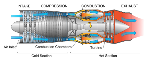
Turbomachinery devices are extensively used as a significant player in most industries such as Automotive, Datacenters Cooling, IT-Hardware, Aerospace and Defense, Energy, Oil and Gas, HVAC, Chemical Processing, and Healthcare.
Significant challenges for delivering the future rotating machines are improving performance and reliability in addition to decreasing the cost. A lot of effort is being made to increase operating range, improve thermal reliability, reduce carbon footprint/emission and minimize noise, vibration and cost as well. Efficiency enhancements can result in global improvements, particularly in the carbon footprint considering more and more stringent emissions standards while devices are being pushed to new operational boundaries. This long list of requirements turns turbomachinery design into a series of convoluted trade-offs which is quite sophisticated to optimize. As a result, most turbomachinery device companies leverage engineering simulation quite often to build in efficiency as they reduce emissions, time to market, and cost while maintaining higher standards of reliability. On top of that, the high cost of prototyping and test in turbomachinery applications makes simulation more favorable. Engineers can refine designs significantly before physical tests are performed, accelerating the process and reducing risk and cost
Simulating turbomachinery applications could be time-consuming due to its complicated and Multiphysics nature. Only Ansys, with its powerful portfolio and its custom-built convenient turbomachinery workflow, is up to the challenge. More and more companies have used Ansys successfully for various rotating machine applications.
- A template-based tool with plenty of parameters
- Extensive embedded empirical data
- Ability to create CAD with minimum input data ( i.e. target pressure ratio, mass flow, and RPM)
- Compatible with Ansys workbench, meshing, and CFD solvers
- Able to connect several turbo parts as a system ( i.e. pump, compressor, volute, etc.)
Fig. 1) Creating 3-D CAD from Best Efficiency Point(BEP) using CFturbo
- Vista is the 1-D Design tool for initial/conceptual design of :
- Axial fans
- Centrifugal compressors
- Centrifugal pumps
- Radial Turbines
- 3-D CAD may be accessed in BladeGen
- Able to create CAD with minimal input data ( i.e. target pressure ratio, mass flow and RPM)
Fig. 1) Creating 1-D initial design in Vista and 3-D CAD using BladeGen in sequel
- Various meshing tools may be used :
- Ansys Mesh
- TurboGrid
- ICEM CFD
- Gambit/TGrid
- May be used for non-bladed components in turbomachinery
- Cavities, inlets, volutes, seals, CHT solids, etc.
- Many mesh types to choose from
- Swept, multi-zone, hex dominant, tetrahedrons
- Some mesh types can produce fully structured hex meshes, depending on the geometry
- Ability to “slice and dice” if necessary
- Highly automated
- Well-integrated


Fig. 1) Several meshing tools available in Ansys portfolio for rotating machinery
CFD Solver
- Fast & scalable solver
- Low speed to supersonic
- Steady/transient
- Turbo-specific BC’s & setup
- Turbulence & heat transfer
- Multiple Frame of Reference
- Multi-phase flow
- Real fluids
- Fluid/structure interaction

Fig. 1) Ansys solvers are very powerful and convenient for modeling turbomachinery devices
CFD Post
- Postprocessor for all ANSYS CFD Solvers
- CFX, VistaTF, Fluent
- Built-in Turbomachine Report Templates
- Quantitative and Qualitative results
- Impeller alone or with volute
- Fully customizable
- Rapid and Consistent Post-Processing!


Fig. 2) Ansys CFD-Post has custom-Turbomachine report templates and wizards which is extremely helpful
The standard workflow for Turbomachinery and a compressor simulation summary is shown in the following:
|
Fig. 1) Ansys and CFturbo workflow for initial design, meshing, and analysis of Turbomachines |
 |
Fig. 2) Ansys and CFturbo workflow for initial design, meshing and analysis of a sample compressor


![Ansys-elite-channel-partner-horizontal-reversed[1]](https://www.ozeninc.com/uploads/2022/06/Ansys-elite-channel-partner-horizontal-reversed1.png)